Search
General Aircraft Monospar

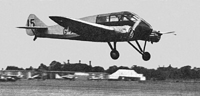
The General Aircraft Monospar was a family of touring and utility aircraft designed and built by the British aviation company General Aircraft Ltd (GAL).
Development
In 1929, the Monospar Company Ltd was formed to pursue new techniques of designing cantilever wings, based on the work of Swiss engineer Helmuth J. Stieger, who headed the company. Helmuth John Stieger was born in Zurich in 1902, and educated at the Swiss Federal Polytechnic, and then at the Imperial College of Science in London. While working as a designer for William Beardmore and Company, he formed his own ideas about wing design, and evolved an improved method of building and stressing wings, for which he was later granted a British Patent in December 1927. The principle behind this Patent No. 306,220 was that the wing needed only one spar with torsion loads resisted by an efficient system of strong compression struts, with triangulated bracing in the form of thin wires. The design was revolutionary and very light for its strength.
Based on this design, the Monospar Company designed a twin-engined low-wing aircraft designated the Monospar ST-3, that was built and flown in 1931 by the Gloster Aircraft Company at Brockworth, Gloucestershire. After successful testing of the Monospar ST-3, a new company General Aircraft Ltd was formed to produce aircraft that used the patented Monospar wing designs.
The first production design was the Monospar ST-4, a twin-engined low-wing monoplane with a fixed tailwheel landing gear and folding wings for ground storage. Powered by two Pobjoy R radial engines, the first aircraft (G-ABUZ) first flew in May 1932, and was followed by five production aircraft. The Monospar ST-4 Mk.II, an improved variant with minor differences, followed with a production run of 30. In 1933, the Monospar ST-6 appeared, a similar aircraft to the ST-4, with manually retractable landing gear and room for an extra passenger. The Monospar ST-6 was only the second British aircraft to fly with retractable landing gear (the first, the Airspeed Courier, was flown a few weeks earlier). Another Monospar ST-6 was built, and two ST-4 Mk.IIs were converted. GAL then produced a developed version, the Monospar ST-10, externally the same but powered by two Pobjoy Niagara engines, an improved fuel system, and aerodynamic refinements. The Monospar ST-11 was developed from the ST-10, with retractable landing gear, and two were built for export to Australia. A production batch of ten Monospar ST-12 aircraft was based on the ST-11, but with de Havilland Gipsy Major engines and fixed landing gear.
The Croydon factory closed down in 1934, and a larger factory was opened in 1935 at London Air Park, Hanworth.
Design
The General Aircraft Monospar was a family of unorthodox touring and utility aircraft. In its original configuration, it was a three-seater aircraft, placing the pilot and one passenger side by side, albeit slightly staggered, while a second passenger could be seated directly behind them. The forward position of the pilot's seat and the absence of a nose-mounted engine meant that forward visibility was exceptionally good. The cabin was furnished with sizable windows that also provided good external visibility, although the occupant of the rear seat has a less generous view, largely due to the low-mounted position of the wing obstructing visibility from that position. The engines were completely enclosed in cowlings, which were arranged so that the airflow (both over and under the wing) would freely cool the engine. Fuel was housed within a single tank within the aircraft's nose, almost directly forwards of the instrumentation panel; it was supplied to the engine directly and was fed by gravity.
The principal feature of the Monospar was its innovative monospar construction method, which was applied not only to the wing but also the fuselage of the aircraft. Accordingly, the structural weight of the aircraft was only 26 percent of the all-up weight, which a considerably lower percentage than was typically found amongst its contemporaries in its size and weight class. For conventional aircraft of the era, the structural weight made up a high proportion of the overall weight of the aircraft; by reducing the structural weight, the ratio of useful payload to all-up weight could be positively increased, meaning that the aircraft could carry a greater useful load without negatively impacting performance. This increase was viewed as being commercially significant, particularly against other competing modes of transport. It was also judged to be valuable in boosting the factor of safety for such an aircraft.
The wing comprised three pieces, the centre section of which was integral with the fuselage and contained the engine mountings, the struts of which acted as the king-posts in the wing bracing system. The wing structure consisted of a single main spar that was strong in its ability to bend but was braced against torsion by two sets of spiral bracing wires, that ran around the wing in opposing directions. The single spar was composed of duralumin and built up from several members to form an I-shaped beam. A supportive web, comprising a plain duralumin plate with triangular holes stamped out for lightness, used a series of lattice bars that functioned as braces between top and bottom flanges. These spar flanges were built up of strips and consisted of angle sections that were riveted to the web with reinforcing cover plates added on the outside. Curved angle sections were used instead of plain flat counterparts, which made them considerably stronger in compression as the curved members that composed it helped to brace one another. Where local reinforcement of the spar was necessary, this can be provided by additional lamination on the outer faces of the spar. The flat spar web was stiffened in places by vertical V-section members.
The spiral bracing used tie rods that were anchored at their ends to the tubular ribs and to plate fittings on the spar flanges where the tie rods of a bay crossed each other; it did not extend out to the wing tips, instead finishing on the spar just beyond the inner end of the aileron. Instead, the false spar that carrying the aileron was used to brace the outer-most wing elements, such as the wing tips. This false spar was at a pronounced angle to that of the main spar, thus triangulating the structure; the former ran inwards from the wing tips, where they are attached to the main spars, to the final compression members of the monospar system via flanged duralumin plates. Additional stiffening of the wing forwards of the aileron was achieved via a pair of hinge ribs. Prise-type ailerons were fitted, which had a fabric covering and a built-up spar on which were threaded diaphragms of duralumin spaced by a flattened tube of duralumin along their trailing edges. The spars are U-shaped and closed with a flanged plate with lightening holes. The wing was built entirely of duralumin, excluding some steel fittings and wiring plates.
A modified form of the wing's monospar construction was used for the fuselage; its primary structure member was a square-section beam of relatively shallow depth, composed of duralumin, that was placed at the bottom of the fuselage and anchored to the wing spar of the center section. The four corner booms of this beam were of built-up D-section and were joined by an outer cover of stamped duralumin sheeting that formed lattices, akin to the main wing spar web. This cover braced the fuselage beam while the free edges overlapped the top and bottom booms. The four booms were kept apart, and resistant to collapse, via a series of tubular distance pieces, both vertically and horizontally placed, that ran between the corner booms. This approach was relatively un-standardised and thus not particularly cheap to manufacture.
The shape of the fuselage was obtained via a series of hoops of trough-section duralumin and stringers (both fore and aft) of similar section. Furthermore, spiral wiring was present to increase the fuselage's torsional strength and make it thoroughly rigid. The result was a fuselage that was free from torsional and flutter-related concerns. The four booms were kept apart, and resistant to collapse, via a series of tubular distance pieces, both vertically and horizontally placed, that ran between the corner booms. The underside of the fuselage was rigidly-braced to the aircraft's tail unit, which was fairly conventional. It had a cantilever fin while both the elevators and rudder were balanced. The stabiliser had a single spar along its trailing edge and triangularly-arranged flanged duralumin plates that ran forwards, along with five duralumin ribs, while the leading edge was formed from flattened tubing. Both the elevators and rudders had similar structures.
The flight controls were duplicated and of the conventional stick and rudder-bar type. The control columns were mounted in forks on the ends of compact fore-and-aft torque tubes that were mounted beneath the seats; these torque tubes were linked together as well as to a lever from which wires ran to the ailerons. The elevators were operated via a torque tube to which each control column was linked through a universally jointed push-pull tube. Wires ran back to a lever on a lay-shaft in the tail unit from where the elevators actuated via a push-pull tube. Actuation of the rudder was via a series of cables that ran directly to the rudder from the rudder-bar.
A divided-type undercarriage with a relatively wide track was fitted. It was highly maneouverable while on the ground, in part due to the use of a castoring tail skid and Bendix brakes; the aircraft could reportedly be kept straight even with only a single engine running even though each wheel was directly under an engine. At least one aircraft had an arrangement in which the brakes were coupled to the control column so that the brakes would activate whenever the pilot pulled back on the stick during a three-point landing; the interconnection could be released whenever the brakes were conventionally operated via a centrally-placed lever. The axles were hinged to the wing girder or main spar on the underside of the fuselage. Each vertical leg, which incorporated a Vickers-supplied oleo shock absorber, were connected to a sturdy point within the engine mounting. A streamline radius rod braced each spring-leg to the wing girder.
Operational history
The Monospar ST-10 prototype (G-ACTS) won the 1934 King's Cup Air Race with an average speed of 134.16 mph. Only one other ST-10 was built.
Variants
- Monospar ST-3
- Experimental cantilever monoplane, powered by two 45 hp (34 kW) British Salmson AD.9 engines; one built.
- Monospar ST-4
- Cantilever touring monoplane, powered by two 85 hp (63 kW) Pobjoy R radial engines, seven built.
- Monospar ST-4 Mk.II
- Improved variant of Monospar ST-4, 22 built, two later converted to ST-6 standard.
- Monospar ST-6
- As Monospar ST-4, with manual retractable landing gear, two built plus two conversions from ST-4 Mk.IIs.
- Monospar ST-10
- Improved variant with two 90 hp (67 kW) Pobjoy Niagara engines, two built.
- Monospar ST-11
- Development of Monospar ST-10, with retractable landing gear, two built.
- Monospar ST-12
- Fixed landing gear variant with two de Havilland Gipsy Major engines, ten built.
- General Aircraft ST-18 Croydon
- Ten-seat transport with two Pratt and Whitney Wasp Junior engines, one built.
- Monospar ST-25 series
- Development of Monospar ST-10
Operators
- Portugal
- Portuguese Navy
- South Africa
- South African Air Force
- Spanish Republic
- Spanish Republican Air Force, 1936 from LAPE
- Spain
- Spanish Air Force
- Turkey
- Turkish Air Force
Civil operators
- Australia
- Australian Transcontinental Airways (ATA), 1935–1936
- Brazil
- VASP, 1933–1938
- United Kingdom
- Inner Circle Air Lines, 1935-1935
Incidents
On 6 September 1935, a Monospar ST-12 operated by Australian Transcontinental Airways suffered engine failure, and made an emergency landing on Woodgreen Station in the Northern Territory. Reports vary slightly, but the plane was said to be carrying the pilot J. Maher, with two passengers, Renfrey and Maloney, and a young crocodile that was being transported to Adelaide. Renfrey walked for two days towards Ryan's Well, a watering hole on the Overland Telegraph Line around 40 mi (64 km), to seek assistance. Three men (one of several search parties sent out to look for the men) motoring across the desert found him, and took him to Aileron telegraph station. In the meantime, Don Thomas from Alice Springs drove to Woodgreen to pick up Purvis Sr and two "blackfellows", one of whom managed to track down the plane based on the description of the location given by Renfrey. Maher and Maloney had only six oranges between them for food, but they survived until they were rescued by shooting and eating the crocodile.
Surviving aircraft
- One Monospar ST-12 (registration VH-UTH) is on display at the Newark Air Museum, England
Specifications (Monospar ST-12)
Data from The Illustrated Encyclopedia of Aircraft, National Advisory Committee for Aeronautics
General characteristics
- Capacity: four
- Length: 26 ft 4 in (8.03 m)
- Wingspan: 40 ft 2 in (12.24 m)
- Height: 7 ft 10 in (2.30 m)
- Wing area: 217 sq ft (20.16 m2)
- Empty weight: 1,840 lb (835 kg)
- Gross weight: 2,875 lb (1,304 kg)
- Powerplant: 2 × de Havilland Gipsy Major four-cylinder inverted inline piston engine , 130 hp (97 kW) each
Performance
- Maximum speed: 158 mph (254 km/h, 137 kn)
- Range: 410 mi (660 km, 360 nmi)
- Service ceiling: 21,000 ft (6,400 m)
See also
- General Aircraft ST-18 Croydon
Related lists
- List of Interwar military aircraft
- List of aircraft of the Spanish Republican Air Force
Footnotes
References
Citations
Bibliography
Text submitted to CC-BY-SA license. Source: General Aircraft Monospar by Wikipedia (Historical)
Owlapps.net - since 2012 - Les chouettes applications du hibou


